February 2006


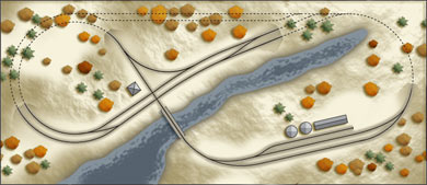
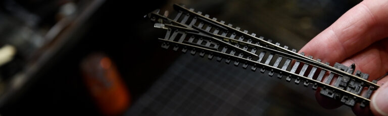
Having spent a number of enjoyable (and relaxing) evenings building turnouts, I became a little more confident about my fabrication skills. As such I started standing over my baseboard and staring at the track plan. I realised that I wasn’t entirely happy with my design, especially the small industry spur. I decided to add a run-around track, and reorient the spur to serve a small industry. Using curved turnouts on either end of the run-around track ensured that it remained a serviceable length, even with the addition of the industry spur. As well, the crossover was originally conceived as an interchange, but there was no interchange track! I added a connection between the main line and the branch line in attempts to create a more prototypical arrangement. I’m undecided if I want to make the interchange a working interchange, or simply build it using dummy turnouts.

Trackplan Revised

The hollow-core door I selected was selected for its availability rather then its dimension, as it was part of a cash and carry sale at a local salvage shop. Although the hole for the doorknob had been drilled through it, the door was structurally sound ‘ certainly sufficient for my needs. Despite that, I added some framing on the underside to allow for wiring, turnout controls etc. The advantages of now having a void in which to run wires, was complimented by having some extra material to attach the future facia as well as the control panel.

I cut some 2x2s out old 2x4s I had in the house on the table saw and attached them around the perimeter of the underside of the door. If not for the 2×4′s, I would have simply purchased some 1×2 pine, or 2×2 spruce strapping. I didn’t bother to mitre the corners, and glued and screwed the lumber into the solid edges of the door. I cut some extra lumber so that I could add some cross braces after I had installed the track and the wires. I laid the door flat on the floor and added some weight around the edges to prevent the off chance of the door warping while the glue dried.

Once the glue was dry, I turned the door back over and removed the Kraft paper on which my ever precious track plan was doodled. As I imagined at least one river on this pike, I attached some 2″ Styrofoam to the entire tabletop. The 2″ foam allows me to make changes in elevation with a steak knife (2 inches of foam translates in 26 scale feet of ground) rather then a reciprocating saw, and gives the model some added rigidity. I had fully intended to use extruded pink/blue foam, however when I was price shopping at my DIY centre and explained my project to the attendant, he offered me cast-off sheet of 2″ 4×8′ white bead foam for two dollars. I didn’t argue with my good fortune. The piece of foam he gave me was for exterior use, and as such was somewhat water-proofed, containing smaller beads then the standard foam. Because of this, the foam doesn’t ‘shatter’ into snow-white shrapnel like its cruder counterpart.

I attached the foam to the tabletop using regular carpenter’s glue ‘ I didn’t have any other adhesives suitable for foam. (Solvent based glues will eat through the foam like a hot knife, giving little or no bond, and leaving you with something that looks like termites ate through it.) Again, I added some weight and gave the whole structure a few days to dry.

Once the glue was set, the combination of the bracing and the foam resulted in a very rigid footprint.

Table

With track plan in hand, I was eager to start laying some rails. However, I was a little discouraged by the cost involved, as well as the possible modifications that would be needed to accommodate prefabricated turnouts. Looking over the meagre supplies on hand, I decided that this layout would be need to be a combination of prefab and hand-laid turnouts. I was fortunate to have a number of PECO set-track switches on hand purchased several years ago when I was going to construct a small shelf layout. The advantage of these switches was that they had very tight diverging radii, and operated reliably. Their downfall was that consequently they have a toy-like in appearance because of this sharp radius, and they have limited uses when creating yards or parallel tracks.

Reviewing my track plan, I determined that I could use the old PECO switches in the hidden staging yards, but the visible tracks would need to be hand-laid. Besides the financial advantage, there was also the benefit that I could create curved turnouts on the return loop, I would be able to build #5 turnouts on the passing tracks, and the diamonds could be made to fit tightly with the interchange track.

Undaunted, I began researching the techniques for hand-laying turnouts, and overall, I was disappointed with the lack of concise material. Fifty years ago, layout builders had to make everything ‘ and I suppose along the way the secrets of turnout construction became part of an oral tradition that I’m just not privy too. I gleaned as much information as best I could from magazines, websites and books, and developed the following method for constructing turnouts.

In order to make the process easier, I built each of the switches on the workbench, planning to later connect them together on the baseboard. I copied the particulars of my plan onto sheets of paper and used these full-size templates to build each of the turnouts.

Overall, I was pleasantly surprised as to how well the switches turned out. Their reliability exceeded my expectations ‘ operating smoothly, with minimal tuning required. On the downside, despite my best efforts, they are not as aesthetically pleasing as the more expensive commercial turnouts. However, with some paint, ballast and other assorted scenic camouflages, they will likely avoid the scrutiny of the critical eye.

After spending several years looking through assorted magazines, doodling on scraps of paper, and daydreaming away hours thinking about my future layout, I realised that when I finally had an opportunity to start designing/building one, I had no idea what I wanted. I certainly knew what I liked and disliked, but when the occasion to start designing presented itself, I was lost.

Being honest about what I wanted was the first step in planning. Over the years I’ve looked over many track plans designed with operations in mind, and I’ve always admired the thoughtfulness and design quality in each. On the opposite side of the spectrum, I’ve poured hours into Kalmbach’s 101 Trackplans for Model Railroaders, in which the majority of designs are considered ‘display’ layouts (commonly featuring continuous running as the primary design element) but have equally admired the designs in spite of their ‘dated’ features. Comparing these two design approaches allowed me to realise that what I really wanted to do was disappear into my basement, work on some scenery, flip the switch, and watch trains roll through my miniature countryside. A continuous running ‘display’ layout was what I wanted.

I refined this decision by including some additional criteria. First, the layout needed to be portable, so I decided the base would be a hollow-core door (I model N scale). Second, I wanted some sort of interchange and hidden staging ‘ replacing the need for active industries. Finally, I wanted to model a freelanced modern Southern-Ontario railway, so the scenery and industry would need to reflect this.

Having established these guidelines, I started doodling ‘ with a pen and paper! I work with computers for a living, and have developed a decent proficiency with many CAD, 3D and Graphical programs. As such, I sampled many excellent layout-planning programs in search of useful planning tool, but found each type of software limiting. I just couldn’t jot down and idea without embarking on a formal plan. Pen in hand, I started to draw. Many of scribbles later I came up with a stack of designs with pros and cons, and ultimately decided on the drawing below.

Trackplan

Sceptical of my ability to draw accurate radii and turnouts freehanded, I refined the conceptual sketch on the baseboard. I covered the door with some Kraft paper, and began re-sketching the design using a compass and turnouts. Several hours later, and after some minor revisions, I had a full-sized plan drawn.

The plan attempts to represent and interchange between a double main-line and a branch-line. Both lines share a simple hidden staging yard, and the interchange becomes a return loop to reverse train direction. There are some flaws in the design, but I wanted to ensure that I kept the track somewhat sparse for scenic effect, so I was willing to live with minor deficiencies.