August 2007


With the landscape contours in place, Pete’s Pumpkins model railroad was finally starting to take shape, thus, it was time to add the barn. Having only previously scratchbuilt structures in N scale, I wasn’t used to the material needs of a large scale structure ‘ I could build and entire N scale city with the styrene needed to build a 1:32 barn! Thus, I chose to build the barn from foam core, as it was significantly cheaper then styrene, and wouldn’t need internal bracing.

Foam core is a wonderful building material; it cuts cleanly, is quite rigid, lightweight, and has the benefit of not melting under the heat of a glue gun.

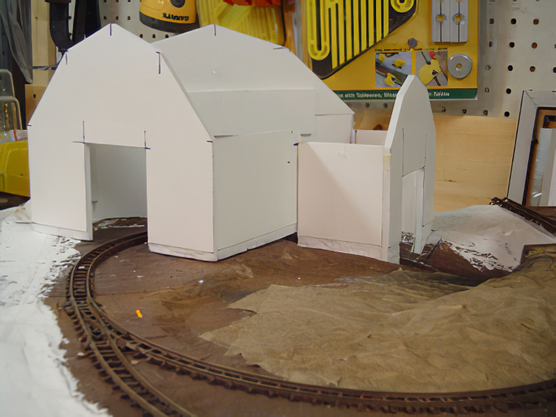
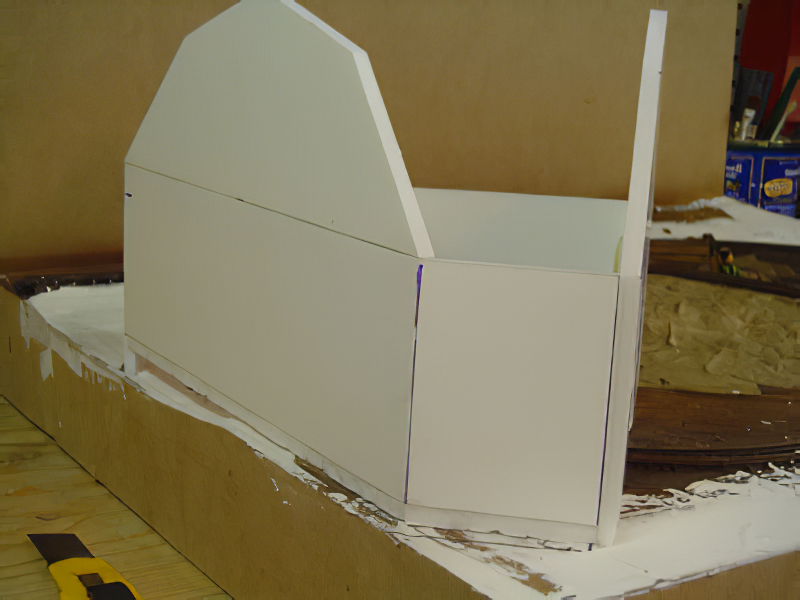
Construction went quickly, and in the course of an evening I was able to build the entire superstructure. The mitres etc. aren’t perfect, but that won’t matter as all of the surfaces will be sheathed in wood siding and metal roofing.

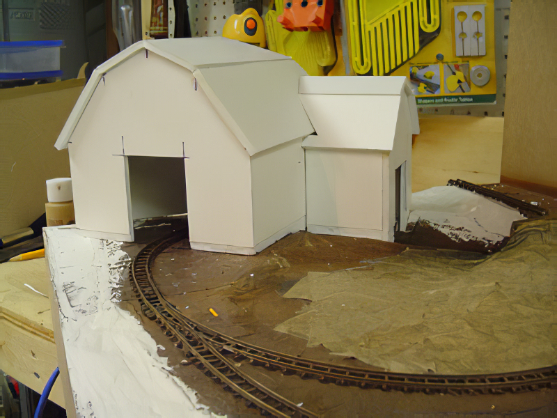
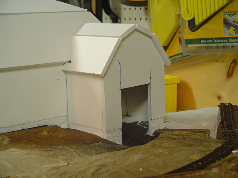
I carved out trenches in the baseboard (another benefit of Styrofoam scenery) and set the barn’s foundations into them so that the rear of the structure was built into the hillside. It was nice to see how the layout will take shape ‘ however I do think that visually things are too heavily weighted to the left side, so I’m going to consider building a smaller building for the rear right corner to help balance everything.


As a member of the Small Layout Design Special Interest Group I was recently introduced to a fledgling group called Snackboxes or SnackTrak ‘ a ‘dedicated’ group of modellers who are toying with the idea of creating a new modular railroad standard based on wooden box sold by IKEA known as the ‘snackbox’. In truth, the group was started on a lark, but interest has been growing as people consider the possibilities of a modular, small/micro layout club. The idea seems to have merit, as it takes into consideration the budgetary concerns of some members, the limited woodworking experience of others, and wraps into a tidy guild that fosters creativity and camaraderie.

Recent discussions have focussed on implementing a standard for the modules. The fundamental problem is that the box is 22″ x 14 5/8″ x 5 7/8″ ‘ offering only a little more then two square feet of modeling space. If you consider the standards that other clubs employ (like Ntrak), you start to realise that too strict a standard will greatly limit modelling possibilities. With this in mind, I’ve put forth the suggestion for a ‘slot-standard’. This idea differs from regular club guidelines by proposing that individual modules need-not be joined inline, but rather they can be offset from one another. Each module could have a horizontal slot cut in the end ‘ just like the handle. Carriage bolts would be passed through the slots, and secured easily with large washers and wing nuts. The beauty of this system is that it builders needn’t worry where their rails are located on the module, only that that they meet the ends of the modules squarely.

Here is the image I uploaded to the Snackboxes group for review. I’m seriously considering building one of these modules! Any takers on starting a local club?

SnackTrak

I managed to finish rouging in the second tunnel portal, and contoured the surrounding landscape.

I stained the wood portals with a mixture of burnt-umber oil paint / varsol, and then lightly over-sprayed everything with black spray paint. (I made sure I stained the wood before I started gluing the surrounding scenery as the glue would resist the stain later.) I applied a thick coat of white glue around the portals an added some loosely wadded balls of paper towel to help flesh-out the hills, and then applied a smooth layer of paper towels and white glue to refine the contours.

Finally, I smoothed out some of the surrounding scenery with drywall mud. I have come to prefer drywall compound over regular plaster because of its working time. Granted, it shrinks and is not as hard as plaster but as I’m not relying on the mud for structural stability, I’m not too worried. It’s also easier to sand, and cleans up very easily.


Having given the track 24 hours to dry, I finished removing the ties in the areas damaged the previous evening without incident, and successfully ran a few test laps with Pete’s Speeder around the oval; all rail joins and turnouts were smooth.

I weathered the ties and rails by applying several light coats of different coloured spray paint, alternating light mists of black, tan and brown. I waited for the paint to dry before scrubbing the tops of the train rails with a fine emery paper, removing the excess paint.

With the track now complete, I focussed my attention to the tunnel. I ripped some scale 6″x6″ lumber on the table saw, and with glue gun in hand, began installing the tunnel portals. A great deal of time and effort was spent trying to create a minimally-intrusive tunnel configuration ‘ bearing in mind that both the upper and lower track levels needed adequate clearances, and the scenery would need to look moderately believable.

By evening’s end I managed to create one of the two portals. The configuration is absurd, as it would have been far more efficient to have simply created a bridge rather then a shallow tunnel, however I like the idea of the speeder disappearing into the ground, and hopefully appropriate scenery treatment will add some believability.


Having managed to install the track the previous evening, I planed to spend this night testing, tuning, and removing / adding ties. I found that there was a kink at one of the joins along the spur at the rear of the layout, so I tried filing it back to scale. This was fruitless, as when I checked the rail spacing, I realized that the rails were about 1/16 too close ‘ far too out of gage to be tuned, so I grabbed the rail nippers and cut the rails behind the joint. It’s at this point the evening started to go badly. No sooner had I cut the rails then the track on the rear of the layout sprang free from the roadbed.

It seems that the caulking didn’t stick to the roadbed.

To explain: I had to raise the grade of the track while I was installing the upper rails, so I decided to try a package of Woodland Scenics roadbed that I had kicking around the basement. This product bills itself as the quieter alternative to conventional cork roadbed, and is significantly cheaper. However, having tried it I can honestly say that I feel this is an inferior product!

Firstly, the roadbed was foam, which is great for sound dampening, but offered no structural support / rigidity for rail spikes etc. Secondly, no common adhesive bonded to the roadbed’s surface. The caulking peeled away easily from the surface, as did the white glue, and CA pooled into a crusty lump. Finally, I don’t know how the surface of the foam is going to react to solvent based paints.

Despite these headaches, I managed to reinstall the track and remove some of the ties on the ‘loop’. I’m very pleased with how well the track turned out around the loop, as the caulking held fast after removing every other tie, and the appearance was very convincing. I will definitely try this technique again on the next layout.

I’ve tried several different ways to lay track, but I haven’t found any technique that is a slick as using latex caulking as an adhesive. The technique is very simple; smooth a small bead of caulking onto the roadbed; pin the track in place; done! The major advantage of this method is the caulking holds everything in place. Caulking is not sticky, but quite tacky, and once the track is set it almost needs no pinning. If you don’t like where the track has been set, pull it up effortlessly, and reposition it. If too much caulking gets on the rails, you can wash it off with water. Caulking is also an effective glue with good adhesion, and once dry becomes waterproof ‘ so you needn’t worry about you track springing free while soaking your ballast in watered-down glue.

It’s important to use transparent latex caulking ‘ as opposed to the standard white. Some of the caulking will inevitably work its way up between the ties, and the transparent caulking will be virtually invisible, whereas the white caulking will either need to be carved away, or painted. On a previous layout, it wasn’t until I started ballasting that I noticed the while caulking peeking through the ties, and it was a real headache to remove!

N Scale Track at 1/32

In 1 Scale, 9mm track has a rail spacing of about 1 scale foot. The ties are 2x3s with an average spacing of about 6 inches. I wanted the ties to be spaced about 12 inches apart, so I chose to remove every-other tie. This was a disaster.

Using my rail nippers, I snipped between each tie, removing every second tie as I went. Once the ties were removed the tracks seemed a little flimsy; the ties freely slid back and forth, and the rails and were quite loose. I figured that once set into the caulking everything would be fine, so I soldered the first section of track to the turnout, bent it around the curve, and disaster stuck! The entire length of rail twisted, and all the ties flew off in every direction. I attempted to snap the ties back on, but each of the little spike heads had been broken off.

I removed the twisted rails (they will make lovely scale scrap) and replaced them with another section of track ‘ ties intact. The sharp curves and steep grades put a good deal of stress on the track, but with enough pins everything held in place. I noticed another advantage of the caulking was that it still offered good adhesion in those places where the ties didn’t quite touch the baseboard.

Some areas of the track only needed an hour before they had completely dried. I took the rail nippers and removed a few ties to ensure that I could achieve the tie spacing I wanted earlier. Success!

I spent the next 10 minutes sweeping up all of the track shrapnel on the floor!


One of the distinct advantages of an all-foam baseboard is that it is fairy rigid, and extremely light. On the other hand, it does stand up very well to normal abuse ‘ dinting and chipping! As I had leftover Masonite from the baseboard, I elected to add fascia boards. I cut each of the boards to size, following the rough contour of the landscape, and then slathered them with white glue and ‘tacked’ them in place with hot glue, taping the corners with masking tape to keep the joints tight while the glue dried.

I wasn’t sure if I was going to add a backdrop, but as I considered my design it became apparent that I needed to frame my scene. I’ve seen layouts by Christopher Creighton and Brian Fayle at local exhibitions, and I’ve always enjoyed being able to view the layouts from all sides. However, the major difference between those layouts and mine is that their designs have a central subject, and track around the perimeter, whereas my focal points are located around the perimeter of the layout with the track. As such, it seemed that framing the scene with a backdrop would be a good idea, and at the very least would lessen the amount of detail I would need to add as now the audience wouldn’t be able to see everything.

(This is a plus as I still haven’t figured out how to deal with my poorly planned tunnel!)


I decided that while I’m trying to figure out track elevations and scenery camouflage, I might as well start thinking about the only structure on the layout ‘ the barn. I drafted the basic contours of a gambrel-style barn in 1:32 scale, and printed each of the plans at 100%. The barn has to fit atop the uneven elevations of the layout, so I added an addition to the side of the main structure to compensate for the rising track.

I’ll make some rough paper mock-ups of the barn, and move it around to see what works best, studying its position while I consider the track…

I wanted to add a front grill to the speeder, but was having trouble finding a decent mesh material. I finally figured out that I could make a really convincing ‘screen’ with polyclay. I rolled some Sculpy out until it was paper thin, and then carefully rolled the knurled handle of my Exacto knife across the surface. The handle left a uniform diamond pattern in the clay which looked just like screen! I baked the clay, cut it to shape, glued it to the speeder and framed it out with some styrene strips. Now the engine won’t overheat!

I decided to paint the speeder with automotive primer as I liked the neutral colour, and I didn’t have any other colours available. Once dry, I sculpted some cushions for the speeder, pressing Pete into the clay to ensure he would sit level. I baked the cushions, gave them a quick coat of paint, and attached them with CA.

I weathered the speeder with some charcoal and real dirt, and fixed everything with some Testors Dullcote.

I’m happy with the results, but have no illusions about what I’ve created. This is not a finescale model; there are no control devices, rivets, and the detailing is crude. I am still looking for something to represent the headlamp, and I need to figure out what I’m going to do with the rapido couplers. That being said, I’m starting to think of this project as a characture more then a model, so I think the design is a good fit for that standard.

My next challenge is to make some rolling stock!


I’ve used foam for landscape contours before, and found the only drawback is that the foam is a bit flexible, so pressure on its surface can cause indents. This is no big deal – unless of course you’ve applied some plaster or spackle atop the foam, in which case it tends to flake off. With this, I chose to apply a coat of full strength white glue and paper towels to the surface of the baseboard. This offered some distinct construction advantages: First, the baseboard is now rock hard ‘ much like a plaster impregnated cloth, the glue/foam has made the surface of the baseboard virtually bullet proof. Second, I’m more confident attaching my track to this rigid surface as it will be more secure then the foam and cardboard alone. Thirdly, it’s important to seal the foam. I will be using spray-paint to colour the track etc., and I really don’t want any chemical erosion on my hillsides.

It is also now apparent that the tunnel I planned doesn’t really have the necessary clearances to look convincing. One option would be to just have one track pass over the other via a bridge, but I didn’t do much detail work on the sidewalls of the tunnel and I don’t want to excavate more material.

Time to head to the sketchbook!

Having finished (mostly finished) Pete and his speeder, I was finally able to calculate the clearances needed to construct the baseboard. The height of Pete in the engineer’s seat was just shy of 2 inches ‘ a touch higher then I would have liked as this meant that the entrance / exit to the Pumpkin Pit would need to be on a 14% grade! I reasoned that this wasn’t a terrible incline for a narrow gage railway as there are examples prototypes railways with steep inclines; the Mt. Albert Tramway in New Zealand for one.

I transferred the original layout plan to a large sheet of boxboard, and then removed the areas between the tracks to create a cookie-cutter style sub roadbed. I traced this template onto several sheets of Styrofoam and removed the areas that corresponded to the tunnel. I glued the two Styrofoam sheets to a 1/8th inch masonite panel using regular white glue, and hot-glued small pine blocks in the corners of the baseboard for facia installation. I next measured the total run of each of the grades and cut out Styrofoam ramps, which I sectioned and again fastened to the baseboard with glue. Finally, I glued the cardboard sub roadbed atop the Styrofoam with a combination of white and hot glue, and temporarily secured the entire assembly with some finishing nails.

I was surprised how quickly I managed to complete the assembly, as well as how rigid the final structure is, and how little the baseboard weighs. Next step: contouring.

Having finished (mostly finished) Pete and his speeder, I was finally able to calculate the clearances needed to construct the baseboard. The height of Pete in the engineer’s seat was just shy of 2 inches ‘ a touch higher then I would have liked as this meant that the entrance / exit to the Pumpkin Pit would need to be on a 14% grade! I reasoned that this wasn’t a terrible incline for a narrow gage railway as there are examples prototypes railways with steep inclines; the Mt. Albert Tramway in New Zealand for one.

I transferred the original layout plan to a large sheet of boxboard, and then removed the areas between the tracks to create a cookie-cutter style sub roadbed. I traced this template onto several sheets of Styrofoam and removed the areas that corresponded to the tunnel. I glued the two Styrofoam sheets to a 1/8th inch masonite panel using regular white glue, and hot-glued small pine blocks in the corners of the baseboard for facia installation. I next measured the total run of each of the grades and cut out Styrofoam ramps, which I sectioned and again fastened to the baseboard with glue. Finally, I glued the cardboard sub roadbed atop the Styrofoam with a combination of white and hot glue, and temporarily secured the entire assembly with some finishing nails.

I was surprised how quickly I managed to complete the assembly, as well as how rigid the final structure is, and how little the baseboard weighs. Next step: contouring

.


When I started this layout, I had no scale preference, just the requirement that the layout would make use of my leftover N scale track, and that it would represent a fictional narrow gage railway. I decided that I liked the proportions of 1/32 scale figures with my track and motive power, as well as the fact that I wouldn’t need to use a microscope to do detail work.

Having decided on scale, I searched online for examples of others doing similar work. I found two things: First, 1/32 scale is not popular. Second, apparently no-one is uses N scale track in conjunction with this scale!

Unconvinced that I was a pioneer in this area, I decided to contact the venerable Carl Arendt ‘ the master of minimum space layouts, to see if he had any thoughts on what sort of designation this scale had.

In his reply, Carl stated:

I haven’t heard of anyone working in 9mm gauge in this scale (though I’m sure that somewhere in the world… ), so you are pretty free to choose your own designation. My preference would be “1n12″ (see my rather arbitrary scale/gauge chart at http://carendt.us/articles/scaleguide.html). OTOH, the small but brave band who are pioneering 9mm gauge in G scale call it “Gnine”. So maybe “1nine”?? It has a nice ring! And of course, the New Zealanders call it “9mil” regardless of gauge — so “9mil-12″ is a possibility, though rather obscure.

Thusly, I’ve officially adopted the 1n12 designation (although I am still partial to the 1nine moniker). If anyone else knows of others working in this scale, please contact me at: onentwelve@gmail.com.

I decided that the most practical design for Pete’s speeder would be a side-saddle design. The motor placement was too cumbersome for Pete to straddle, and I was trying to minimize the unit’s overall height as much as possible. I took one last look at the drawings, discarded them, and started scratchbuiling.

I built a shell around the motor and drive using plain styrene. I was careful to ensure that shell didn’t interfere with the worm gear, while snugly fitting around the tops of the drive wheels. Using my thumbnail as a ruler, and some photos from Gn15.info (currently under construction) I ‘imagineered’ (and revised) the speeder’s dimensions until it looked like a plausible diesel unit.

Happy with the basic form, I went hunting for some detail parts. Scrounging about it my toolboxes produced some vinyl zip-ties, a 3M wire connector and some cable clips. Perfect! These bits of junk became the bumpers, exhaust pipes and the light manifold.

More to come!


Satisfied with modelling job from the previous evening, I gave Pete a quick coat of paint. Using inexpensive craft paint purchased at the dollar store, I first primed Pete with a coat of white, and then applied successive coats of various colours until I had blocked in his basic features. I emphasized some of the highlights in his clothes by lightening the original shades and dabbing them atop the original colours until I was satisfied with the coverage ‘ my goal was to use paint to distract from some of the modeling defects.

Finally, I watered down some burnt umber paint, and washed it onto the figure ‘ paying particularly close attention to the facial features ‘ and dabbing the excess with a paper towel, until Pete’s features were clearly visible.

I’m happy with the way the figure turned out. While I can only see his flaws, I do know that from a comfortable distance he looks good, and is somewhat more believable because of his muted colour scheme, and dull sheen.

If time permits, I’ll attempt to add some additional figures to the railroad, perhaps even a scarecrow. Until that time, I have dozens of pumpkins to model!

Next Page »