One of the fun things about these little audio segments I’ve been recording is that they feel more like a journal than a podcast. They’re immediate, unpolished, and kind of important to me because they sit between the public side of the hobby — the modeling, the YouTube videos — and the private side, which is just me thinking things through. Recording them makes me more mindful, and when I look back, they trace this journey of where my thoughts are at.
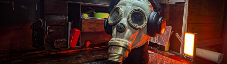
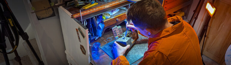
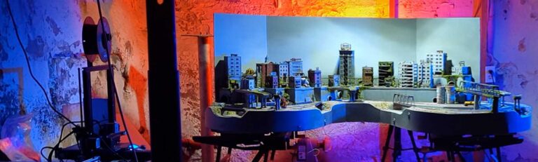
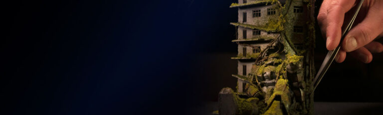
Lately, a theme keeps coming up — I catch myself waxing poetic about “the way things used to be.” And I’ll be honest, that feels a little frightening, like a marker of getting old. But what I’m really circling is this idea that joy often comes from the act of doing, from sitting down at your workbench or kitchen table and getting lost in a project. That feeling when time just disappears and you’re immersed — that’s one of the best parts of the hobby.
Now, YouTube has become part of that hobby for me too. It’s not about money, it’s just another way of engaging. Making videos keeps me honest, gives me deadlines, and helps me actually get things done. But at its core, what I love most is still that sense of working through a challenge and coming out the other side.
And here’s where I get stuck: everything around us keeps getting more efficient. In life, in work, in medicine, in hobbies. Tools and software make things faster and easier, which is great — time is money, and if you can save time, you either make more or you free up hours for yourself. And in model railroading, it’s no different. Look back to the 1950s issues of Model Railroader and you’ll see people with full machine shops in their basements, turning their own drivers on a lathe. Today, you can buy just about anything online or 3D print it in an afternoon.
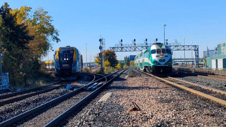
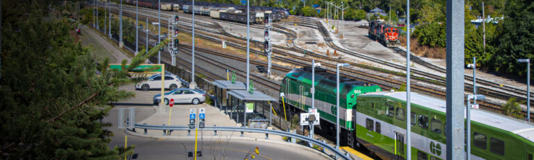
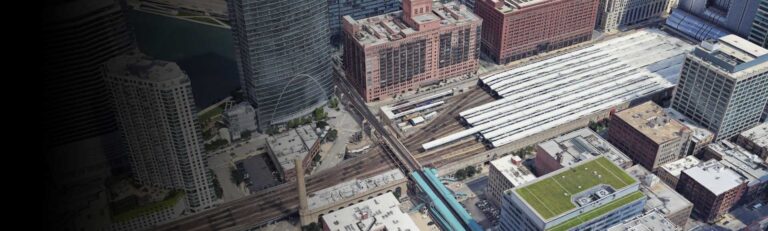
That brings me to last week. I tried out one of those AI programs that turns a single photo into a 3D model. The process was simple: take a photo, upload it, download the STL, tweak it a bit, and print. I took a shot of a little electrical building down at the rail yard. Within an hour and fifteen minutes I was holding a miniature version in my hand. If I’d scratchbuilt it, it would have taken a couple of hours. If I’d modeled it from scratch in CAD, same thing. But this way? Practically instant.
And I’m not sure how I feel about it. On the one hand, it’s amazing — futuristic even. On the other, it makes me uneasy. Because there was a time when to do that you needed to know photography, CAD, modeling, and a whole lot of craft. Now all those steps collapse into one click. It doesn’t cheapen my background exactly, but it makes my own long journey feel less unique. That’s a hard feeling to shake.
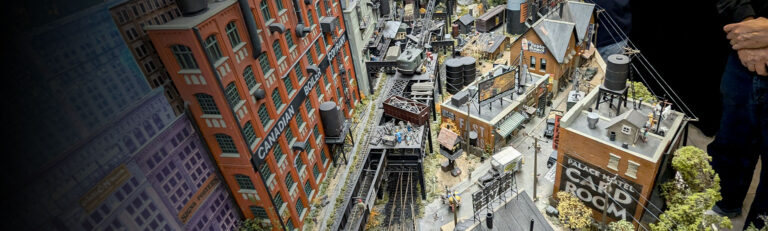
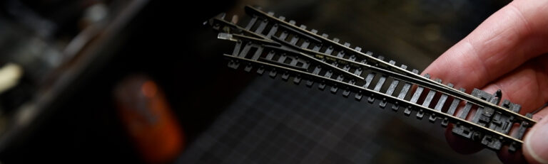
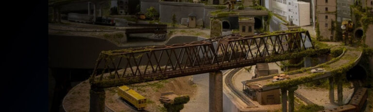
It reminds me of how people look at track: some use Kato Unitrack because it’s fast and reliable, others insist on flextrack and hand-laid rail because it feels “real.” There’s always this spectrum — efficiency on one end, deep craft on the other. Neither is wrong, but they each shape the experience.
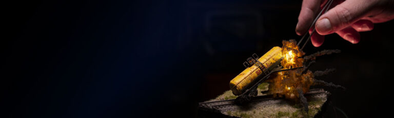
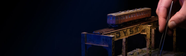
And I guess what I’m wrestling with is this: when technology removes the struggle, it risks removing the joy. For me, some of the deepest satisfaction has come from the challenge itself — the slog, the hours, the overcoming. At the same time, I don’t want to sound like I’m against new tools. I love experimenting. Just last week I also scrap-bashed some beer can toppers into ventilation shafts for my underground station. That’s the complete opposite of AI 3D scanning, and yet both were fun in different ways.
So maybe that’s the balance. For me, technology is great and I’m absolutely going to keep using it. But the real joy — the part that sticks — is still in the doing. And that’s not me being prescriptive, that’s just how I feel about my own journey.